””

Traditional industrial design sliding door hardware kit on heavy duty flat track.  Different from other manufactures in that it only takes 4 1/2" room over slab to fit complete kit, stand-off spacers and axle assembly more versatile and adjustable to get door tight to wall and install track straight, heavier 1/4 x 2" flatbar, option in multiple colors and with or without holes drilled in track, custom nylon wheel with double ball bearings.

10% off satin nickel or rust bronze, free shipping up to 7' lengths

$346.00 CAD

Extras


Installation Instructions

  • Read these instructions to end before starting installation or ordering hardware. 

    Reclaimed Lumber Products (RLP) warrants this hardware is free of defects and is guaranteed for ten years if installed properly. Customer misusing hardware voids warranty. Hardware must be installed correctly in appropriate application with supplied materials. There must be appropriate structural backing and support to hold lag screws which mount track. Track failure is most likely to happen from incorrect or insufficient attachment of screws to wall. RLP is not liable for any accidents or damage caused by incorrect or insufficient installation. Warranty does not cover normal wear on finish especially where wheel rides on track. 

    Track is rated for up to 400 lbs. total hanging on track. Do not allow persons to hang on door and slide on track. All structural support must be solid enough to support load. Attachment only to paneling or wallboard is not sufficient to hold track. Mounting screws must sink into studs or wood headers. A continuous solid wood header is preferred. 

    This hardware is not recommended for exterior installation. 

    RLP is not liable for any accidents or injury result during the installation of this product. Customer and installer should take proper safety precautions when using hand tools and power tools. It is up to the operator to know how to use tools properly, safely, and effectively. 

    RLP takes pride in their products. Please provide pictures and feedback of your finished product. Thank you for choosing RLP. 

  • Track 

    5” x 3/8” lag screws (1/2” hex head). Here are the recommended numbers of lag screws for each length of track: 6’, 5 holes; 7’, 6 holes; 8’, 7 holes; 10’, 8 holes; 12’, 10 holes; 13’, 10 holes; 14’, 11 holes. One stack of 3/8” spacer washers about 1 ½” tall and one 3/8” fender washer for each lag to work as stand-offs for each mounting hole.

    End stops: two 1 ¼ x 1 ¼” rubber bumpers with ¼” x 1” socket head bolt and nut.  

    Two carrier assemblies. Wheel is mounted to carrier with 2” x 3/8” bolt with spacer washers that can be moved on axle to adjust for thickness of door. Additionally there should be four 3/8” bolts, eight washers, and four acorn nuts to mount hanger plate to door. Use 2 ¼” bolts mounting bolts for 1 ¾” doors and 2 ¾” bolts for 2 ¼” doors. If other door thicknesses are used adjust bolt sizes accordingly. 

    3” long x 1” tall floor guide and two mounting screws. 

    Two plywood wide spacer blocks (1 ¼” wide and 1 7/8” wide) for setting carrier assemblies on door to drill for mounting holes in door. 

  • 3/16” allen wrench 

    ½”, 9/16”, 5/8” socket or wrench 

    1/2” nut driver for drill or socket for mounting lags 

    Drill, punch, 3/8” drill bit if mounting holes need to be drilled in track, 1/8” drill bit to pre-drill for lags and floor screws, 3/8” drill bit for boring holes in door 

    Level 

    Pencil 

    Tape measure 

    Stud finder 

    Philips screwdriver or bit for drill 

    1/4” slotting cutter and router or circular saw 

    Step ladder 

    Clamp 

    Safety glasses and other proper safety equipment and precautions 

  • Clearances Needed

    The default setting to centerline of wheel is 7/8” from back of hanger. Move washers around on axle if necessary to have center of wheel from back of hanger plate to be half the thickness of your door so the door is centered front to back under the wheel. One can also adjust how well the door hangs plumb by moving the spacers on the axle, but make sure both wheel assemblies have equal number of washer spacers on both sides of wheel. If door is hanging to where bottom of door is leaning into the wall remove spacers between wheel and hanger. Floor guide will be necessary to make door hang plumb. 

    There are stacks of thicker washers and fender washers supplied to act as stand-offs that go between track and the wall. The mounting lag goes through the center of this stack. If you use all the supplied spacers the centerline of your track will be about 1 3/4” off wall. Do not use more spacers than enough to make back of track 1 ¾” off wall; greater than this distance is not recommended do to safety concerns with mounting lags. You need to calculate how much clearance you need behind door in relation to any trim or other protrusion in path of sliding door. The mounting bolts supplied to mount hanger to door reduce clearance by about 5/16”. If this is a problem, you can countersink bolts into back of door or substitute carriage bolts. If you do not have enough clearance, you can also add a ledger board behind the track as a spacer; make sure this is securely mounted so as to not compromise the attachment of the track to the wall. You can also add more washers as spacers on axle. Sometimes this changes how the door will hang plumb, though. 

    The adjustable stack of stand-off spacers should be evenly matched in height for each lag. Use as few as possible of these to achieve the desired spacing for track off wall so that the door has only about 3/8” clearance behind door. You can use this formula to calculate the different variables: 0.375” (clearance behind door) + (any obstruction such as door casing, baseboard, switches, etc.) = (distance from centerline of wheel to face of door or back of hanger) – (thickness of door) + (distance from centerline of track to wall). The best variable to adjust is the distance from centerline of track to wall by adjusting the height of your stack of washers that act as standoff spacers; this can be adjusted in 1/16” increments. 

    Provide clearance under the door (minimum of ¼”, but recommended ½” - ¾”). Over the top of the door 4 3/8” clearance is needed for wheel to spin freely. 

  • We recommend a minimum of 1” of overlap on all three sides. These drawings below show 2” on sides, 1” on top, and ½” gap under door for demonstration purposes. 

    More overlap ensures the door will cover the opening better and not allow as much gap to show around the edges even if not shut fully. 

    To calculate door slab width on single door add overlap on side times two plus inside dimension of opening. 

    To calculate door slab width on pair of doors take half of inside dimension width and add one side of overlap dimension for each door slab. 

    To calculate door slab height take inside opening height subtract desired gap under door and add desired overlap on top. This could place the track over any trim that is over the top of the opening. Either the door slab needs to be adjusted in height so track can go above trim or trim needs to be flat and fully extend for full width under track. 

    Note all these dimension are easier to calculate if opening is just a sheetrock opening with no trim. You need to consider what the trim will look like with door in open and closed position. How much of the trim do you want showing if any at all? 

    For door height be sure to consider where the mounting lags need to go for the track. They will be centered about 1 1/8” over top of door slab. Be sure there is proper backing and load support for lags to attach to at these points. 

    A factor to consider is that it is easier to size your door in six inch increments so that the track length is exactly twice the width of the door. This makes install simpler. 

    Conversely another factor to consider with the flat track is that it needs to be firmly attached to the wall right up to the end of the track. If you do not have backing in the wall for the last lag screw within 3” of the end of the track, you may need to buy a longer track so it can reach the next stud of attachment point on the wall. In this case you may want to just move the end stops in closer to the center. 

  • Installation Steps

    1
    2
    3
    4
    5
    6
    7

    Decide how you want the floor guide to be installed. If you want the alternative option shown in picture with double guides, be sure to order an extra floor guide. Otherwise cut a 1/4” wide kerf centered in bottom of door. To determine depth of kerf cut, subtract desired gap under door from 1” and add 1/16”, so for a ½” gap under door you would have a 1/4” wide and 9/16” deep slot/ kerf. This is easiest to do with a router and a slot cutter. 

    On a single door the guide is centered on the track from left to right. In any case, the door needs to cover at least half the floor guide whether it is in the full open or fully closed position. Install the floor guide to the floor. If the door properly overlaps the opening, then the floor guide should not protrude into the opening. 

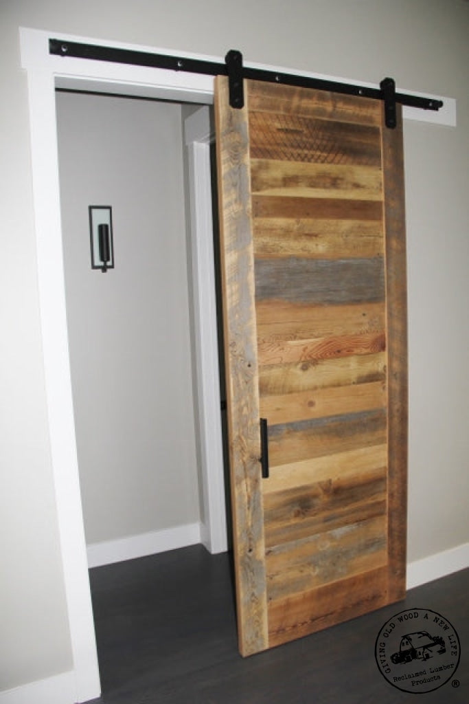
    f you mount outside edge of carriers 1 ¼” in from edge of door, this will have edge of door stop flush at end of track based on predrilled stop holes in track. The bolt hole rubber bumper stop is drilled 5/8” in from end of track to center of hole; the rubber bumper is 1 ¼” in diameter. Utilizing our predetermined pattern plywood spacer block with edges of carrier 1 ¼” from edge of door (bolt holes 2 ½” from edge of door is center of carrier) will allow for a track to work that is exactly twice the dimension of the door slab. This pattern will also center the carrier on a 5” wide stile. Here is a formula you can plug in different values if you like to calculate track length: (Door Width) + (Distance From End Of Track To Center Of Stop Bolt Hole) - (Distance From Edge Of Door To Edge of Carrier) + 5/8” = Track Length / 2 For double doors on a single piece of track just don’t divide the formula by 2 at the end. 

    You can plug different scenarios into the above formula to calculate all different options to make the track work for your door size. The 1/4” stop hole can be re-drilled in another spot if would like to change mounting points or have door stop in different spot on track. For example you could drill ¼” holes 1 5/8” in from end of track and still mount carriers 1 ¼” in from edge of door; this would allow you to use a 47" door with an 8’ track (47 + 1.625 – 1.25 + 0.625 = 96 / 2). Alternatively in this scenario you could cut the track shorter, too. 

    Also you could mount the carriers 4” in from edge of door (or 5.25” to center of carrier) and utilize an 8’ track for a 50 ¾” wide door without changing stop holes (50.75 + 0.625 – 4 + 0.625 = 96 / 2). Note with this scenario your door will stick past the end of the track by 2 ¾”. Make sure to consider how the carriers will look in relation to frame on the door regardless of where you choose to mount them. 

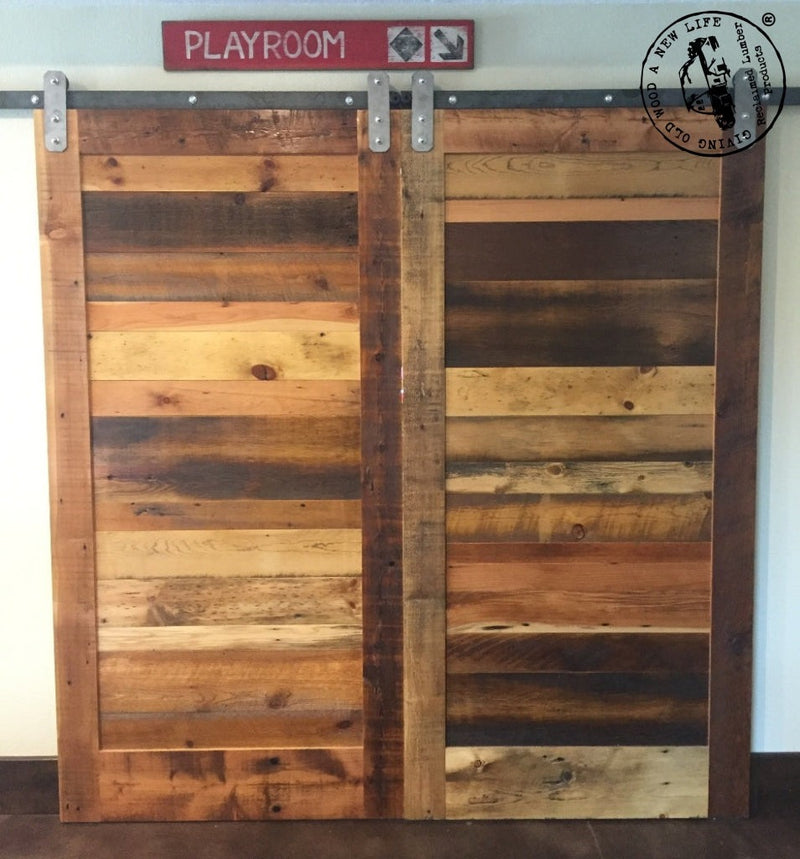
    On double doors with a single track you can also add stops in center of track to make sure doors stop in the middle. Double doors that always stop in the middle can also just as easily be done with two different sets of track. 

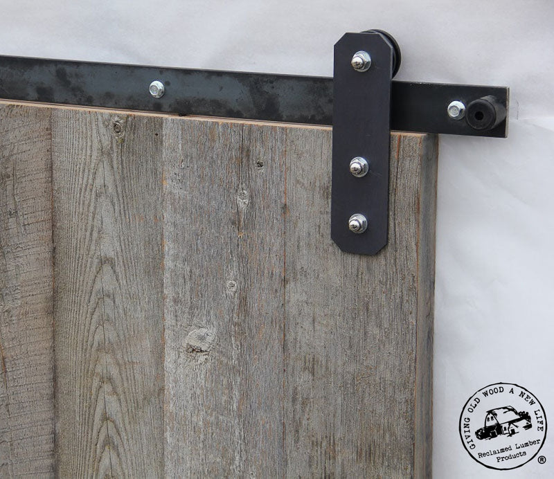
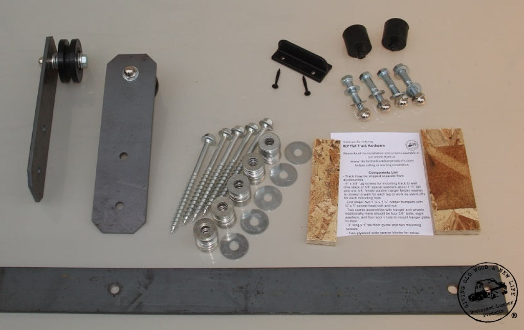
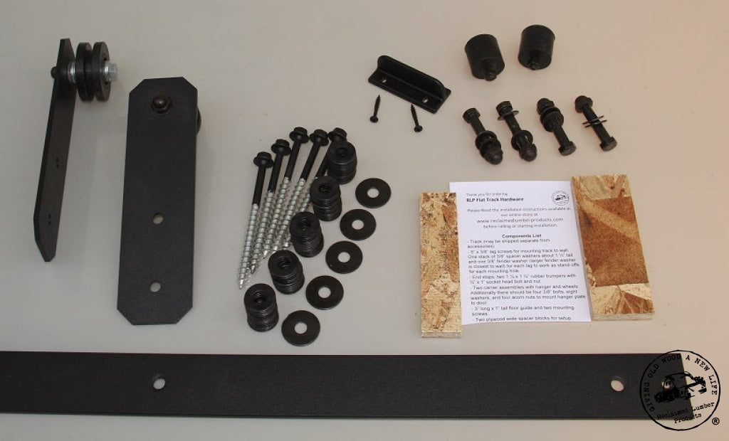
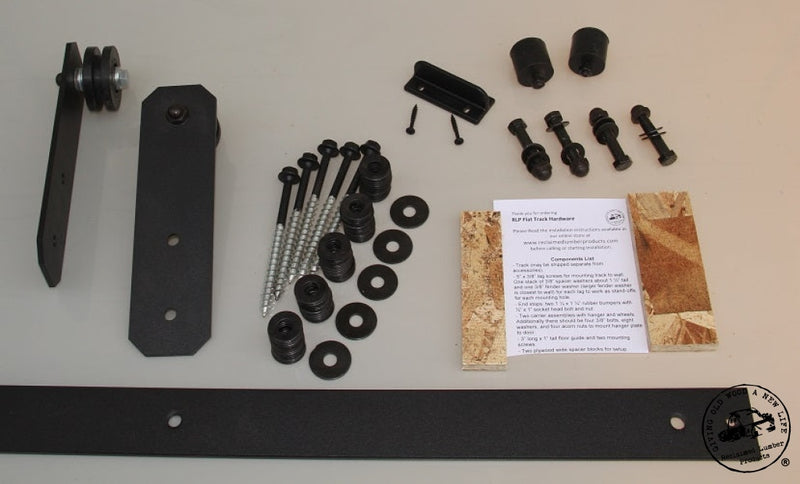
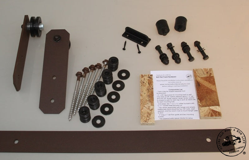
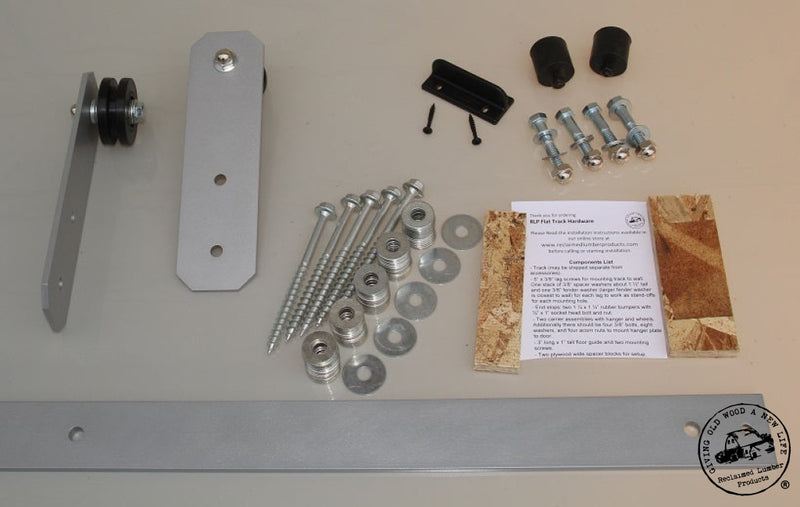
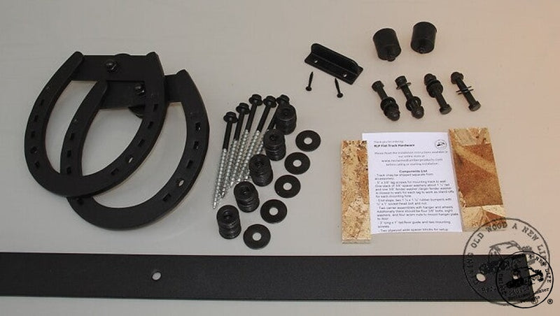
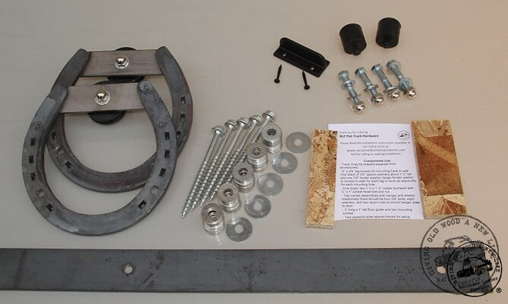
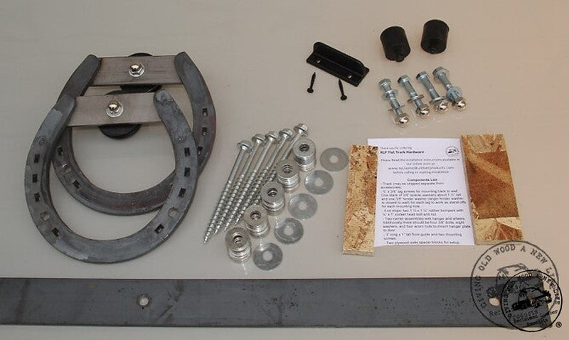
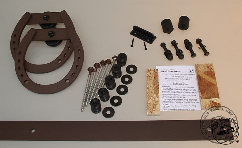
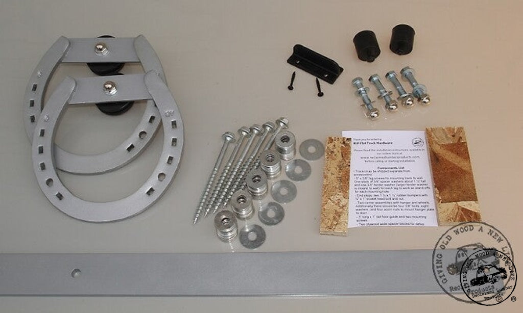
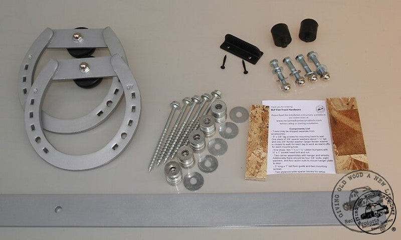
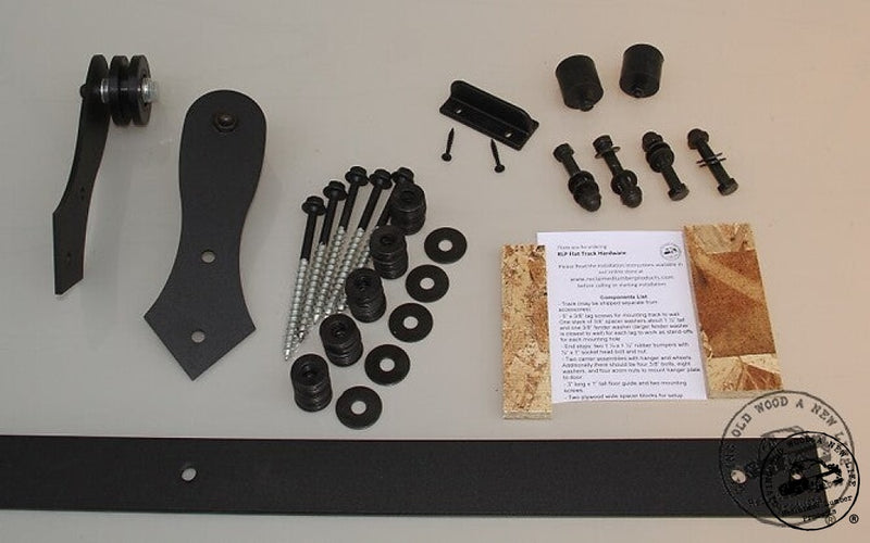
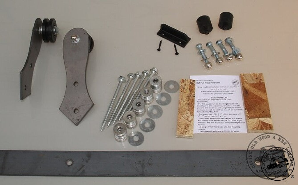
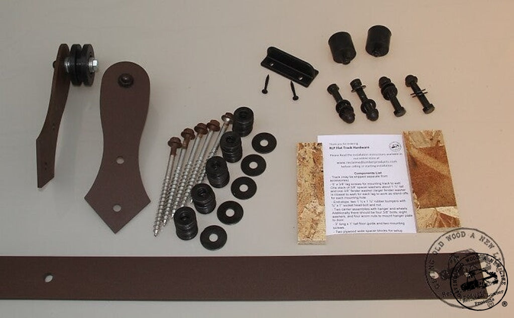
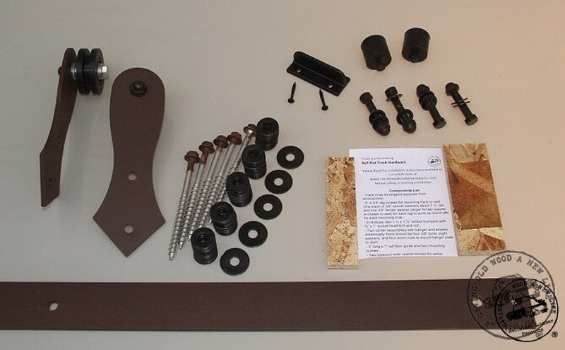
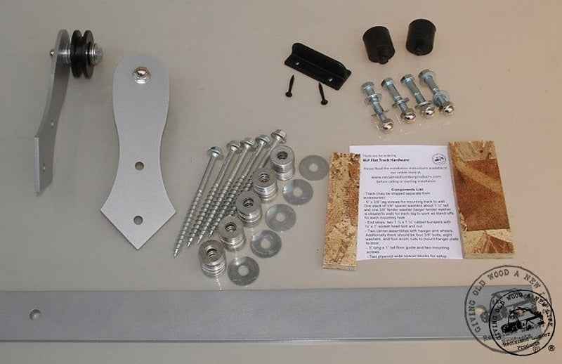
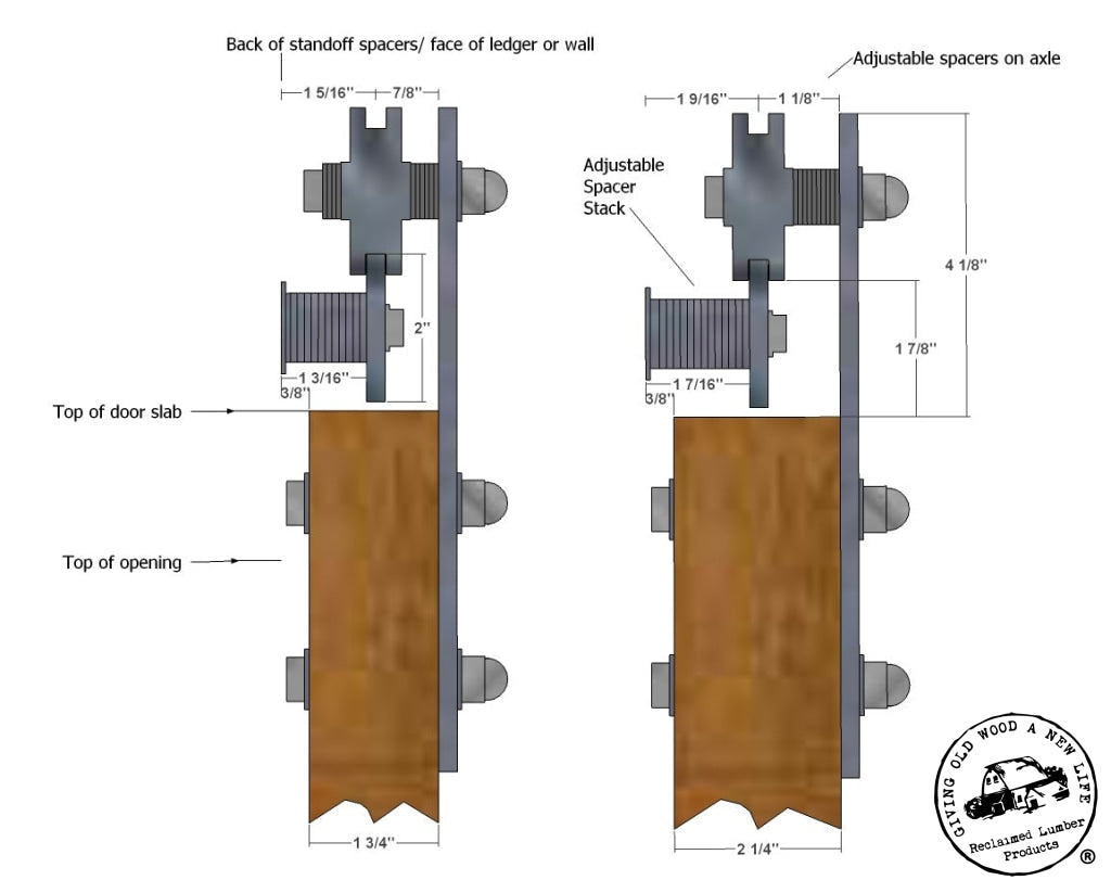
    Make sure complete carrier/hanger assembly is assembled with wheel, spacers and hanger. Normally the distance from back of hanger to center of wheel is approximately half the thickness of the door. Refer to the cross section drawing on page #3. Be sure to have the bolt that is the wheel axle in the appropriate hole. This hole is the one furthest from the other two on the hanger. The two holes for attaching to the door are the pair closer to each other on the hanger’s bracket. The washer that goes under the 3/8” acorn nut on the front of the hanger is the same size as the washer supplied with the two pair of mounting bolts used to mount the hangers to the door. 

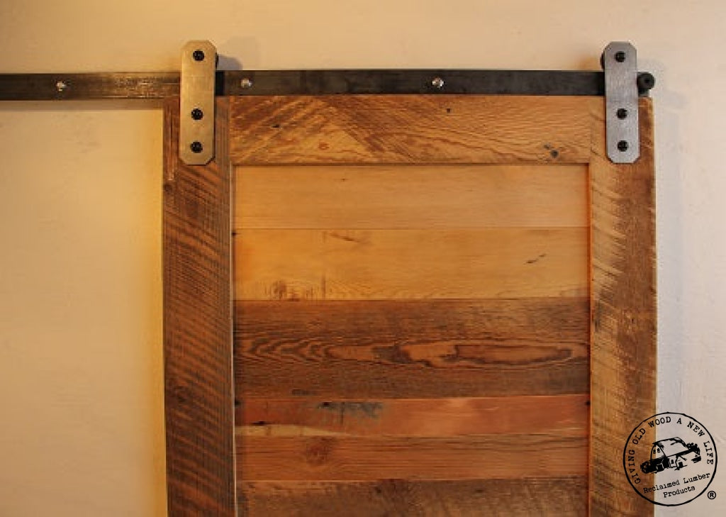
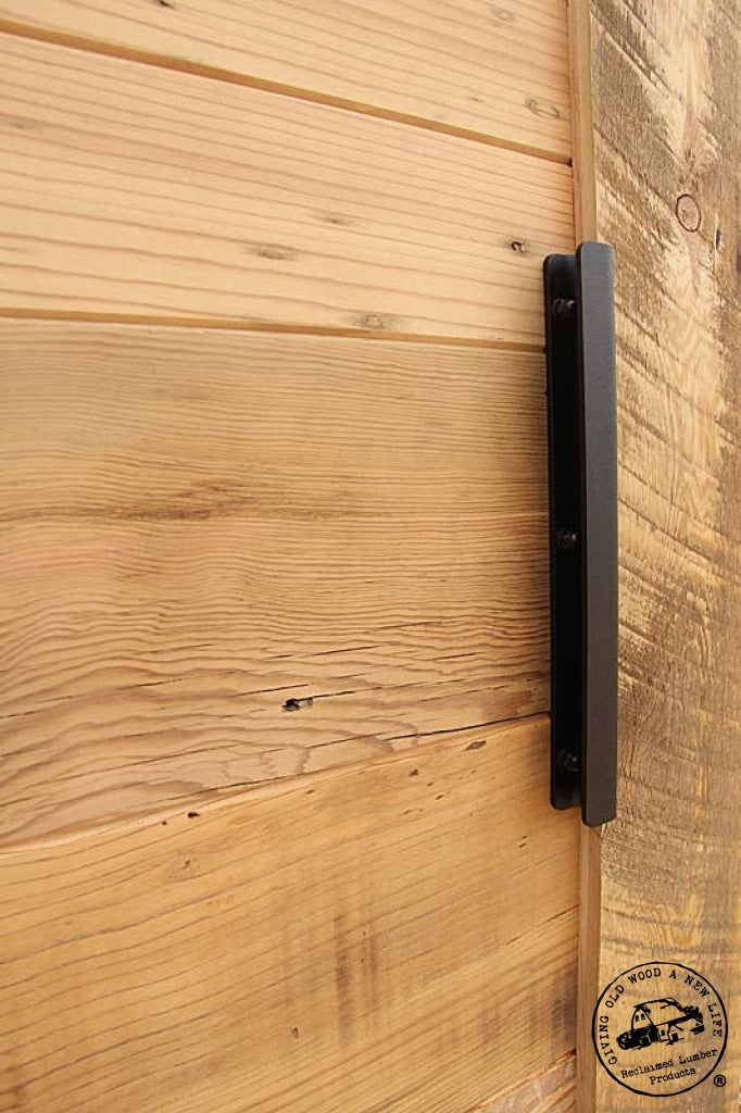
    Using supplied plywood guides flush narrow 1 ¼” wide piece up against edge of door (only works with rectangular shaped hanger) and the other 1 7/8” wide piece on edge against top of door. Then hold carrier tight to edge of piece on face of door and wheel tight to piece on top of door. The dimension from bottom of wheel to top of door is critical that it stays this recommend gap of 1 7/8” (the height of one of the plywood spacer blocks). This is a safety and proper functioning issue. This gap makes sure that the door and carrier assembly fit on track properly, slide smoothly, and do not “jump off” track. Holding these three pieces secure, temporarily clamp carrier/ hanger assembly to door making sure to leave two bolt holes clear. Make sure to have wheel side of carrier facing to center of door and verify that carrier’s metal strap is square to door. 

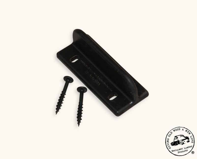
    Use 3/8” drill bit to drill both mounting holes in door slab using the steel carrier plate as a guide. Be sure to drill straight and perpendicular to door face. Now repeat procedure for the other side. 

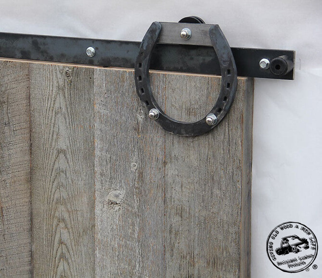
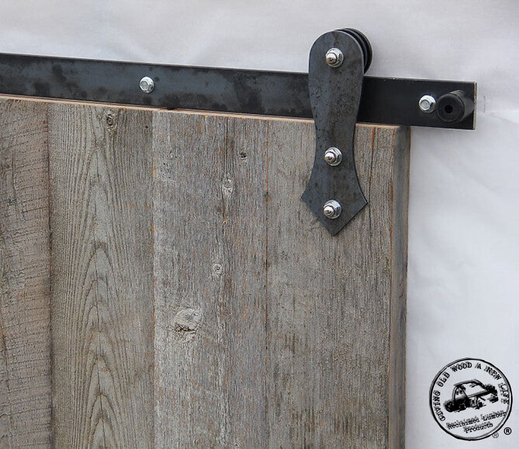
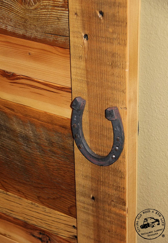
    NOTE: The above step for using the plywood guide on the face of the door will not work as well with the arrow, horseshoe, or any custom shaped carriers; with these just measure from edge of door 1 ¼” to edge of hanger that will come into contact with the rubber bumper on the track or substitute the measurement from the above equation. You must still use the plywood spacer to set wheel height above door, though. 

    NOTE: You can order track that is any length you want even though the rule of thumb is twice the door width. If you don’t have room for this, and you have made all the adjustments you can by moving carriers and end stops then the door just won’t fully open from closed position. Alternatively you can order track longer than you need if it helps with finding better attachment points for mounting lags; the end stops can be reinstalled to stop the door short of where it  normally has the door edge flush with end of track. If the track is ordered and installed too long between stops, then the floor guide won’t function properly. In this case you may want to order and install multiple floor guides so the door slab does not jump off a floor guide in the situation where the travel distance for the door is greater than twice the door’s width. 

    At this point you may want to consider painting, staining, or finishing your door slab if necessary. Allow proper curing before handling door. 

    Determine distance from floor to bottom of track by adding gap under door + height of door slab + 1/8” (reference drawing at beginning of instructions) and top of track is 2” higher. The lag screws will be center 1” down from the top of track. Mark these measurements on wall on each end of track location. Verify and adjust if need be with a level. Mark where end of track will be. 

    Note you want track installed level, but floor may not be level. Verify height points from floor along full length of track to be sure you have proper clearance. Keep track level and raise height if need be to get clearance. Also be sure that floor guide will reach door properly after setting height of track. As a note of caution, the lags and spacers tend to sag up to about 1/8” when installing heavy doors. When installing doors over 100 pounds you may want to add an extra 1/8” into the height of the track to anticipate this and be sure it will work with your floor guide clearance. There is also a note below for the proper way to install lag screws. 

    If you did not order predrilled track (predrilled track should only be used if you have continuous backing in your wall), locate all mounting points within full length of track on wall. Note that flat track cannot cantilever and stay rigid past last lag installed at end of track. If end of track is more than 3” past last attachment point you need to install backing or order longer length track to pick up an additional mounting point at end of track. If installing longer track then you can move end stops in closer. 

    Use stud finder if need be and mark each point on wall that is going to be a mounting point. With extra set of hands hold track up against wall and transfer mounting hole marks to track. If you cannot hold track up against wall, measure from one constant end to each hole. We recommend a minimum of five lags per section of track and spacing of around 16”. Drill your holes from backside of track so you do not mar the finish. It is best to start hole with a steel punch for ease of starting drill bit. Center holes 1” down from top of track (reference drawing at beginning of instructions). Minimum hole diameter is 3/8” when finished. 

    Determine which side of track looks best. Some tracks have imperfection in the finish and metal. Orientate the best face out. 

    Remember all mounting holes need to be in structural support. With drilled track verify it matches mounting points mark on wall. Reference beginning of instructions on clearance issues. Determine how tall you want your stack of standoff spacers; you do not necessarily have to use all the washers supplied. Make even stacks for each mounting hole. It is critical that all spacers are the same height to begin with! Make sure there is one larger fender washer per stack; this washer is the one that goes closest to wall. Push one lag through each end of the track, and put one stack of washers on each. Go ahead and sink both lags into permanent positions. Check that everything is still level now that track is mounted on wall with a lag in each end. 

    Now you can predrill with 1/8” bit all holes in center of track using track mounted on wall as a guide. Note this takes a long drill bit. If you do not have a long enough drill bit to do this make sure to mark and predrill these holes before installing track on wall. Be sure predrilled holes do not slope downward towards floor. If anything they should angle slightly upwards instead of ninety degrees to wall. Your standoff spacers and lag screw may tend to sag after installing door on track. This will become more pronounced with heavier doors. To compensate for this you can install lag screws at a very slight upward angle. 

    Install all lag screws with spacers. As a tip to make install of stack of spacers/ washers easier, you can wrap with tape to keep them together while sliding behind track. Then the tape can be removed after install. After installing you may find that your wall was not flat; if this is the case, you can go back and add extra washers in low spots to compensate and make track straight. Another hint when installing color coated lag screws is that the powder coat color can be easily chipped off. If you use a impact screw gun it may knock the color loose. It is better to carefully tighten lag screw with a socket or wrench taking care not to chip off color. If you do lose the color you can touch up with paint later. 

    Install rubber stop at one end of track. Leave most accessible side of track open. 

    Bolt carrier with 3/8” bolts to door. Use acorn nuts on front, carrier side of the door. If you have clearance issues in back this when you need to substitute 3/8x16 thread carriage bolts or countersink existing bolts. If countersinking or removing washers you may need to cut bolts shorter or substitute so they work with acorn nuts. 

    Now for the fun! Slide door onto track on free end of track without stop. Install other stop. Do not slide or operate door without both stops installed in each end of track. 

    Note for tracks installed in tight spaces with no space at open end of track you may need to take wheels off of carrier. Alternatively you could also mount one complete hanger and bolt the second one to the face of the door after everything is in place on the track. Prop door vertically with shim blocks under door accounting for gap under door. Now set wheel into track and bolt wheel and axle assembly back onto carrier. This method is not preferred or as simple as installing complete carrier assembly on door slab before sliding slab and wheels onto track. 

    Congratulations; you did it! Enjoy. It will last a long time. 

  • Proudly made in the USA.
  • Custom designed by RLP meant to function better and install simpler with more flexibility than most flat track.
  • Wheel spacing from hanger is adjustable.
  • Stand-off distance from back of track to wall is adjustable to allow the installer to install a straight track on uneven wall or adjust clearance to have back of door as close to wall as possible.
  • Heavy duty all steel construction with ball bearing wheels.
  • Unique design for rubber bumper stop bolted on end of track- no metal on metal clang!
  • Ultra long lengths (many custom options available) of barn door hardware track stocked in sizes up to 14" as a one piece track with no splices. Alternate brands sell long length options in multiple pieces rather than our one piece track.
  • Alternative design than most flat track and doesn't need jump blocks installed to keep wheels on track.
  • Can be order with or without mounting holes predrilled in track so you can match the track to the mounting points available on the wall.
  • Complete kit for track includes all hardware you need to mount your door. You do not need to purchase any extra lags or other fasteners.
  • Colored kits are coated with matte textured, industrial, baked on powder coat- not spray painted like many other brands.
  • Save money by combining this track kit with a one of our barn door slabs for an additional $85 discount (discount applied at final checkout).

  • Grooved wheel with sealed ball bearing for long life and smooth ride.
  • 400 pound capacity per track.
  • Requires 4 1/2" of clearance over top of door slab.
  • Spacers supplied allow adjustment for stand-off distance from wall to back of track to be 3/4" to 1 9/16" (adjustable in 1/16" increments). The track can be mounted on a ledger board to increase this distance off the wall (or consult with us for increasing quantity and length of lags to even allow greater stand-off distance).
  • The hangers are 9" tall and extend down from the top of the door about 5". Note instructions for different spacing with horseshoe hanger.
  • All mounting bolts are 3/8".
  • Track is made from ¼" x 2" flat-bar and hangers are made with 3/16" thick steel. (note our track is thicker than some other options offered with other manufacturers)
  • Please note if you are ordering the Unfinished Bare Raw Steel option for color it has no seal coat or finish on the raw steel. The steel may have rust and discoloration. It is raw steel with varied colors shiny silver, dull grey, to rust pitted. The different components may not match exactly in color with the unfinished option. Most customers order this option for an industrial look, or they intend to finish themselves with another treatment.

  • Track has stop holes predrilled. For installations with a solid header order predrilled mounting holes in your track; otherwise for installations with inconsistent mounting points order track with no mounting holes so you can drill to match your layout. Normally you should order track twice the width of your door.
  • 3/8" x 5" timber lag screws in the quantity matched to length of track you ordered. These lag screws are stronger than standard ½" lags and are just the right size for the application; they are not so big that they blow out studs when trying to mount track to studs. Corresponding adjustable spacer stack to mount under track with each lag screw.
  • Two rubber bumper end stops.
  • Two carrier assemblies which include hanger plate; axle; spacers to adjust depth of wheel; ball bearing wheels; mounting bolts corresponding to your thickness of door; washers and acorn nuts.
  • Floor guide is black, 3" long, 1" tall, and made with 3/16" thick glass filled nylon. Floor guide is meant to be screwed to floor with two black #8 screws supplied (alternatively could be epoxied to floor or over concrete customer may need to supply concrete anchors. Recommendation is to mount door ½"-3/4" off floor.
  • Two wood spacer blocks for easy install of carrier assembly to door slab.
  • Not included - Installation, door slabhandleprivacy lock, or tools.
  • No anti-jump blocks are required because of the unique design of track and installation method.

  • Four color choices standard: raw unfinished steel along with these textured powder-coat colors black, rust bronze and satin nickel. Please note that these pictures are of the actual product but the color may look different in person than on this screen. Also note that we make no representation that our color name matches any other manufacturer's color.
  • Track lengths are 5-14".  We may be able to manufacturer in longer lengths or cut to size other lengths of track than what are shown here.  Normally you should order the track length at twice the width of your door, but do not cantilever the flat track more than a couple inches past your last mounting point. If you do not have a stud or backing in the wall as an attachment point close to the end of the track, you should order a longer track and move the door stop in from the end of the track.
  • Specify the thickness of door mounting on this track so we supply the correct length mounting bolts. The bolts supplied are typically 1/2" longer than the thickness of the door.
  • If you are doing two doors per track, order kit for 2nd door on single track. For example this would be mounting two 2' doors on a single 8' track. Alternatively for larger byparting doors with one opening to the left and one to the right such as two 3' doors just order two complete 6' track kits.
  • For non-standard installations we can adjust the size of the track's lag screws to be longer depending on requirements of track distance off wall and thickness of wall.

  • RLP warrants this hardware is free of defects and is guaranteed for ten years if installed properly.
  • Customer misusing hardware or not following installation directions voids warranty.
  • Warranty does not cover normal wear and tear especially on finish.
  • All products sold by RLP are non-refundable and non-returnable since most are made to order.

Video